Import DWG
AutoCAD DWG are drawing files that while not largely intelligent in terms of the equipment and data displayed on them, are widely used today.
The first step of the import is to define the source and destination locations
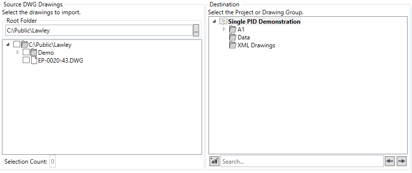
The system remembers the last location the user imported from, a new source location can be selected via the ![]() button, Folders/DWG files to import are selected via the checkboxes
button, Folders/DWG files to import are selected via the checkboxes
The destination folder to import to is selected via the right hand tree.
The next step is to select the import options
![]()
There are four import options
- Import Structure - Imports the drawing in the same folder structure as it exists in the source
- Create Source Folder Root in Destination - Creates the source structure in the project root
- Skip Existing - Skips already imported drawings
- Version Drawing - Versions the drawing as part of the import process (drawings imported from HDX can be worked on graphically in the Aurelia tool)
The DWG Conversion Options are as follows
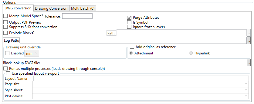
- Merge Model Space - Used during the import non-native DWGs to attempt to reduce the number of paths by merging overlapping lines into single items.
- Output PDF Preview - Outputs a PDF of the DWG as a preview
- Suppress SHX font conversion - Does not try to convert internal SHX fonts to Truetype fonts. Use if the conversion does not work as expected
- Explode Blocks? - Explode block symbols into their constituent parts automatically
- Purge Attributes - Limits the attributes transferred to the converted drawing to the minimum number of attributes required for Hazid Integrity to operate
- Is Symbol - Processes the DWG as a drawing or symbol, drawings are processed as multiple items, symbols are processed as single items
- Ignore Frozen Layers - Skips the import of graphics/data on layers that are "frozen" in the DWG, including in nested blocks
- Log Path - Allows the user to specify the location to which the logs are written
- Drawing Unit Overrride - Allows the user to override the drawing units and specify their own, used on legacy DWGs drawn with inconsistent units
- Add Original as Reference - Allows the user to add the original DWG file as a reference to the imported data, as an attachemnt or hyperlink with a log path available to be specified
- Block Lookup DWG File - Allows the user to specify the location of a DWG file containingblocks to be used for the replacement of shapes
- Run as Multiple Processes - Allows the user to specify that the import is to be run over more than one windows process
- Use Specified Layout Viewport - Allows the user to specify the page layout and size for the DWGs being imported - legacy DWGs are often variable is size/scale.
The Drawing Conversion Options should be set next
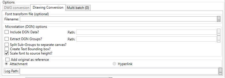
- Font Transform - Allows the user to specify a new font for the imported drawing, by slecting it via the broswe button
- Include DGN Data - Allows the user to import external microstation data from a specified location, merged into the relevant items.
- Extract DGN Groups - Allows the user to save the uniqure DGN groups to a specified folder
- Split Sub-Groups to separate canvas - Extracts sub blocks (labels, etc) into their own layer and item.
- Create Text Bounding Box - Creates a bounding box around text on its own layer
- Scale font to source height - Scales fonts to try to match the source docuemnt scaling. This can adversely affect the final vertical position of the text.
- Add Original as reference - Allows the user to add the original DWG file as a reference to the imported data, as an attachemnt or hyperlink with a log path available to be specified
- Log Path - Allows the user to specify the location to which the logs are written
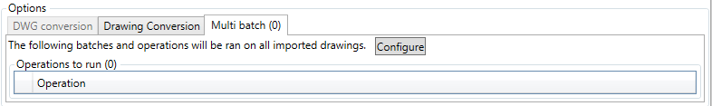
Multi Batch Operations can be configured via the ![]() button
button
The ![]() button imports the drawing(s),
button imports the drawing(s), ![]() closes the dialog.
closes the dialog.