Ports & Propagations
Ports act as the connection between model Items in Hazid Integrity and Propagations drive the abnormal deviations through the Process Safety Simulation.
Ports
A Model can store multiple ports for different Inlet and Outlet configurations as needed for the process item you are modeling.
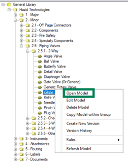
Models require ports to map process connections to. Go to Knowledge Bank, right-click the model in the model tree and select ‘Open Model’:
This will open the Model Overview window:
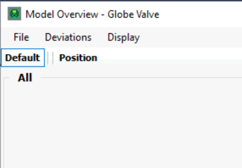
Double-click on ‘All’ to open the ‘Model Summary’ window:
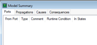
At this moment, no ports are available. To add ports, select one of the options from the following list:
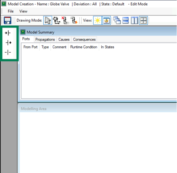
The available options are inlet  , outlet
  or internal
  . Drag any of the options into the Modelling Area window, irrespective of position. When the port is placed, the Port Properties window will open:
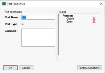
In the case of minor components with two connection points, the inlet port should be called ‘In1’ and the outlet called ‘Out1’ to allow the auto port mapping to work.
Initially ports only apply to the default state (or the state you are working in), thus both the ‘Closed’ and ‘Open’ states will be crossed out  . To include all states here, this must be changed so that both states have a
  next to them. Simply click on both states to apply the changes.
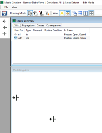
Components and equipment with more connections will require more ports, although not every equipment connection will require a port other than the connections involved in the work process. Ports are only used for process connections, meaning that components that have signal connections will not require ports.
When all necessary ports have been added, click the save button  and close the model summary.
Propagations
Propagations stat and end at Ports and connect together to create Propagation chains. A Propagation deviation can change to another deviation and can work in reverse of the flow direction.
To add propagations open the Model Overview window on a model that has ports and deviations assigned to it:
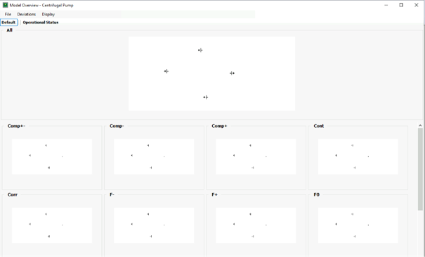
There are also tabs for each state that will show only the propagations active on that state:

To edit the propagations, double-click on the “All” preview. This opens the Model Creation window:
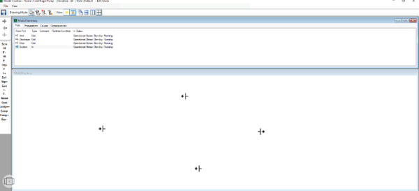
Propagations are made between ports (and on a port itself). To add a propagation, first select the deviation from the list on the left hand side of the window

Then click and drag from the start port to the end port:

When the link is completed the Propagation Properties window opens:
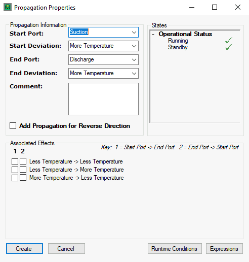
The Propagation Information describes the propagation and allows you to change it. This also allows you to propagate from one deviation to another, e.g. more flow->more level.

The States list allows you to choose which states the propagation is applicable to. Clicking the tick/cross will enable or disable it in that state.

Below that are options to easily add conjugate propagations:
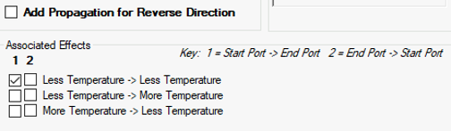
“Add Propagation for Reverse Direction” creates the same propagation but running from the end port to the start port – useful for deviations that can propagate against flow direction such as flow rate and pressure. In addition, the other combinations of keywords and directions for the variable are listed.
Click “Create” to add the propagation(s). They will then be represented by a vector (black is a single propagation, blue is multiple propagations) in the modelling area and will be listed in the propagations tab:

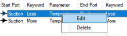
Right-clicking on a propagation in the list allows you to edit or delete it.
Repeat this process for all the deviations required by the model.
Deviation Filter
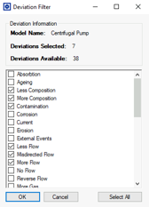
There can be many deviations in a process safety library however not all deviations are applicable to all models, to ensure only the relevant deviations are shown in the model builder we apply a filter to the model.
To assign the deviations to a model open the model overview window and select “Deviations > Filter Deviations” from the top navigation bar:
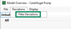
This will open the Deviation filter window where we can enable and disable the deviations with the checkboxes to the side of the deviation, enable as necessary and press “OK” to apply them:
Runtime Conditions
Runtime Conditions are used to set the conditions under which a Propagation, Consequence, Cause or Port are triggered and used by the system.
While they are available on Causes and Ports, they are most commonly used on Propagations and Consequences, to define the detailed propagations that are allowed through a port, or that trigger a consequence.
They are accessed by clicking on the  button in the Propagation, Consequence, Cause or Port Creation/Edit Window to open the runtime editor window:

Clicking the  button will open a window where we can select from the 7 options available, if we have more than one condition we can use the conjunctives (AND, OR, NOT) to define how they relate to one another.
The runtime conditions available are:
- FirstUnitEntryPort - This run time allows you to set the port and propagation of entry into a model for a consequence/propagation to be allowed.
- NotFirstEntryPort - This run time is the opposite of the above - a propagation is allowed if it does not come from the specified port & propagation
- FirstEntryPortIsThis - This run time only allows a consequence/propagation to occur/propagate from the inital port on which the consequence/propagation is created.
- FaultUnitIsConsequenceUnit - This run time will only allow a consequence to be shown if the cause of the consequence is the same unit.
- NotFaultUnitIsConsequenceUnit - This run time will only allow a consequence to be shown if the cause of the consequence is not the same unit.
- IsSameFault - This run time allows you to only have a consequence/propagation activated by a particular cause.
- NotIsSameFault - This run time is the opposite of the above - a consequence/propagation is allowed if it does not come from the specified cause
FirstUnitEntryPort/NotFirstUnitEntryPort require you to enter the Deviation and Port through which the propgation Must/Must not enter the model through. (This must exactly match the text in the deviation/port, otherwise the runtime will not work correctly)
IsSameFault/NotIsSameFault require you to enter the Cause Descriptor that the originator of the deviation chain Must/Must not be. (This must exactly match the text in the Cause Descriptor, otherwise the runtime will not work correctly)
For example, a pump would have cavitation and dry running as a consequence for no flow from upstream, and a different overpressure of discharge consequence from no flow downstream, so the FirstUnitEntryPort runtime can be used so that the consequence is only triggered when the deviation comes in through a particular port.
The pump also has a No Flow cause on itself for failure so the NotFaultUnitIsConsequenceUnit runtime will ensure that does not erroneously result in dry running.