Batch Processing
Overview
The Batch Process Manager allows you to create and administer batches of processes in order to largely automate the conversion/remediation of dumb drawings into fully intelligant engineering data sources.
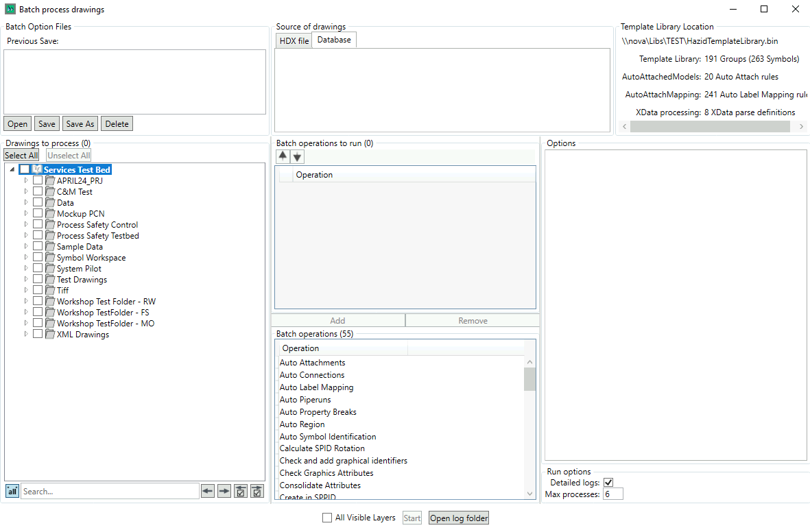
There are seven main sections to the Batch Manager
- Batch Option Files - The Batch file manager
- Source of Drawings - The Drawing Source Manager
- Template Library Location - The Template Library information panel
- Drawings to process - The tree where you select the drawings you wish to process if you are running a batch (batches can be created and saved for future use without having to run them)
- Batch Operations - The panel in which you define which batch operations you wish to run, and the order in which you wish to run them.
- Options - This Panel contains tabs with the batch operation options of those batch operations that you have specified (not all batch operations have tabbed options)
To run a batch, either load a batch file or create a batch operation instruction list, select the drawings on which you wish to run the batch and click the  button.
The  checkbox limits the batch operations to only run on layers that are currently set to be visible in aurelia.
The  button opens the folder location that the logs are defined to be written to
Batch Option Files
The Batch Option Files Panel allows you to load batch files

The  button accesses a folder browser where you specify the location of the batch xmls that you wish to create/work on.

Double-clicking a batch in the list opens it.
The  button saves your batch to the currently selected batch
The  button allows you to specify the xml file to which you wish to save your batch to.
The  button deletes your currently selected batch.
Source of Drawings
The Source of Drawings panel allows you to specify the source from which you wish to populate the Drawings to process panel.

The "Database" tab is shown by default, with the "Database" tab selected, the drawings to process tree shows the drawings available to you in your current project.
Selecting the "HDX file" tab changes the view

Here you specify and input and outut location, either with the button or by entering/pasting in the folder location. Note that the input/output location can be the same folder, which will enable the "I confirm that I want to override the input HDX files" checkbox, enabling you to replace the HDXs once they have had the batch operations run on them.
Drawing To Process
The Drawings to Process panel allows you to select the drawing(s) that you wish to run the batch operation against.
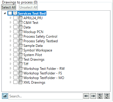
Use the checkboxes to check in/out the drawings you wish to run batch operations on
The  /
/  buttons select or unselect all the drawings in the tree.
The search function can be used to search the tree
If you have selected the "HDX File" tab in the Source of drawings panel, the the tree is simply a list of all of the drawings present in the fold that you have selected.
Batch Operations
The Batch Operations Panel is used to define the batch operations that you wish to run, and the order in which you wish to run them
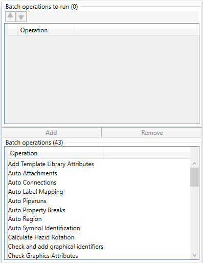
To add an operation, select it and click on the  button
To remove an operation, select it in the top panel and click on the  button

Batch Operations are run as an instruction order as if they were being run manually, so any changes an instruction makes are "last one wins" except for where the instruction does not overwrite existing data. As such, they can be moved up and down the instruction order with the  buttons.
There are a maximum of forty three operations available if the drawings are in the database, with thirty six operations being available for HDX file drawings.
| Name | Description | Options |
|---|---|---|
| Add Template Library Attributes | Updates the Can Attach/Connect/Break Piperun, Never in Piperun and Maximum Connections attributes based upon the model the graphic is mapped to | ✅ |
| Auto Attachments | Runs the Auto Attachment Rules defined in Drawing Editor | ✅ |
| Auto Connections | Runs the Auto Connection Rules defined in Drawing Editor | ✅ |
| Auto Label Mapping | Runs the Auto Label Mapping Rules defined in Drawing Editor | ✅ |
| Auto Piperuns | Runs the Auto Piperun generation rules defined in Drawing Editor | ✅ |
| Auto Property Breaks | Automatically inserts line breaks between the items to which a break label is attached | ✅ |
| Auto Region | Automatically generates regions around graphics for equipment creation | ✅ |
| Auto Symbol Identification | Automatically identifies equipment from regioned graphics | ✅ |
| Calculate Hazid Rotation | Calculated the Hazid Rotation attribute of the imported equipment | ✅ |
| Check and add graphical identifiers | Generates graphical identifiers for all graphical items that do not have one | ❌ |
| Check Graphics Attributes | Runs the Routine to Check and Remediate the attibutes that define the graphical items | ❌ |
| Create in SPPID | Exports the drawing automatically into SPPID | True |
| Create Piperuns from Attributes | Creates piperuns based upon the attributes that identify them, and breaks them where those attributes change | True |
| Export SPPID FULL Background Symbol | Exports the entire drawing as an SPPID background file | True |
| Export SPPID Background Symbol | Exports the drawing border and title block as an SPPID background file | True |
| Export to AutoCAD | Allows you to export the currently open drawing to a specific location as an AutoCAD .dwg file | True |
| Fix Connections | Repairs connections that have a connectedpipingpoints attribute that is incompatible with their number of true connections | ❌ |
| Fix Piperuns | Repairs piperuns that have an equipment order different to the connections within them | ❌ |
| Generate Branching Points | Runs the routine that generates the connection and model detail where pipes/lines join or split | ✅ |
| Identify Centrelines | Runs the centreline identification | ✅ |
| Output to HDX | Allows you to export the currently open drawing to a specific location as a Hazid .hdx file | ✅ |
| Output to PDF | Allows you to export the currently open drawing to a specific location as a .pdf file | ✅ |
| Prepare for SPPID Injection | Runs the SPPID injection preparation routine | ❌ |
| Process Xdata Attributes | Creates Aurelia attributes from the contents of the drawing Xdata attributes | ❌ |
| Recalculate Graphical Identifiers | Recalculates the centre, extents, width and height attributes for graphics | ❌ |
| Remove orphaned attributes | Removes attributes that have no parent item | ❌ |
| Remove Orphaned Branches | Removes branches that have no connections | ❌ |
| Remove Orphaned Equipment | Removes equipment that has no parent drawing | ❌ |
| Remove Regions | Removes regions from graphics | ✅ |
| Replace Graphics | Replaces Graphics in the drawing | ✅ |
| Re-sequence TextBlock attributes | Re-sequences textblock attributes to a logical numbering system (TextBlock1,2,3...) | True |
| Set layer visibility | Defines which layers are set to visible by default based upon your selections in the Options Panel | True |
| Snap Lines to Grid | Snaps the lines on the drawing to the grid based upon your selections in the Options Panel | True |
| Split Blocks | Splits the graphical blocks into sub blocks based upon your selections in the Options Panel | True |
| Split Selected Pipe By Inline Items | Allows certain inline items to split piperuns, these are defiend based upon your selections in the Options Panel | True |
| Split TextBlocks from graphics | Moves text blocks out of graphics and into their own item | True |
| Sync piperun data | Creates and updates grouped piperun equipment | ❌ |
| Synchronise equipment identifier attribute | Synchronises the ID attribute with the equipment id and removes the now-redundant EquipmentID attribute | ❌ |
| Update attributes from mapped models | Updates the Model Name and Model Path attributes from the model that the graphic/text is mapped too | ✅ |
| Update piping/signal attributes | Updates the piping/signal identifers and numbers of connections | ✅ |
| Update Text | Synchronises all TextBlocks with their VTextProperty attribute (the text to be displayed) and adds it if it is missing | ❌ |
| Update TextBlock Attributes (Rotation, Font, Size, Model) | Updates the rotation, font and size attributes of all text equipment, also defines the Model Name and Path for text that does not have those attributes | ❌ |
| Update TextBlock Graphics | Trims whitespace and resizes text block areas to fit the text within them | ❌ |
Batch Operation Options
When certain operations are selected, their batch options will be displayed in a tab in the Batch Operation Options panel
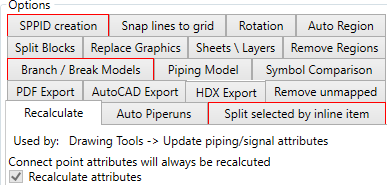
Each batch option requires additional information for performing the operation, these will be defined in the options section after the operation has been added to the list of operations for the batch.
Run Options
The Batch Operations Panel is used to define how certain batch operations function, as well as the standard run options for the batch process, which are as follows

There are three selecitions here:
The log folder location, defined either by pasting/typing into the box or loacted via the button.
The detailed log generation checkbox, checking it generates more detailed logs.
The Maximum concurrent processes window (default 6) - this is the maximum number of processes that the batch processor will use, we recommend it be one less than the total number of threads available on the machine.
Setting "Max processes" to "1" sets single threaded operation.