Piping Model Tab
The Piping Model Tab is used to set the options for the "Identify Centrelines" Batch Operation
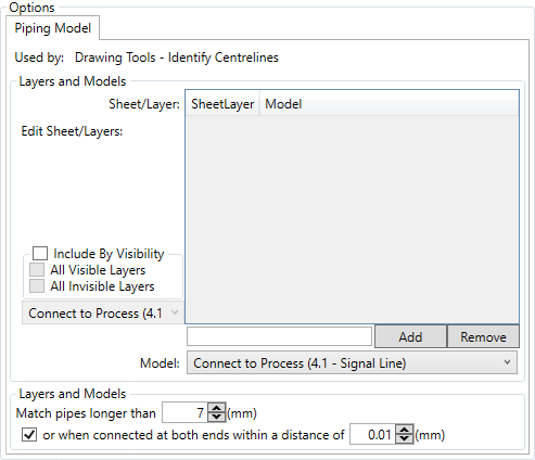
To make an identification for piping routing you must define the layer and sheet

Then click the ![]() button.
button.
With a sheet\layer added, left clicking it and selecting the model you wish to map centrelines to sets that selection
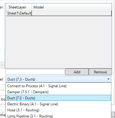
Like so

Clicking the ![]() button removes the currently selected line from the list.
button removes the currently selected line from the list.
If the drawings that are being operated on are simple, then the include by visibilty checkbox can be checked.

This allows you to map all centrelines on visible layers, all invisible layers, or both to a single line type model, selected from the drop down.
There are three additional options to be defined

These options enble you define the minimum length of line to be considered a piece of connector, in order to exclude flanges and break indicators, by defining its length, and the connectivity and gap size that means that two items are connected in reality.