Identify Centerlines
In competently drafted drawings, different line types (primary piping, secondary piping, utility piping, pnematic lines, canbus, electrical cables etc) are split out into different layers, the centrline identification manager uses this (where present) to quickly and easily automate the identification of these connectors based upon their layer.
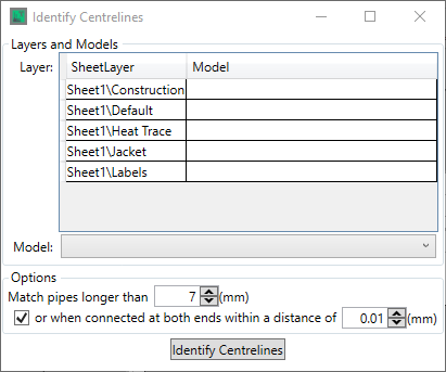
To identify the centrelines on a layer, select the layer with a left-click and then use the Model drop down to select the line model that you wish to identify centrelines as
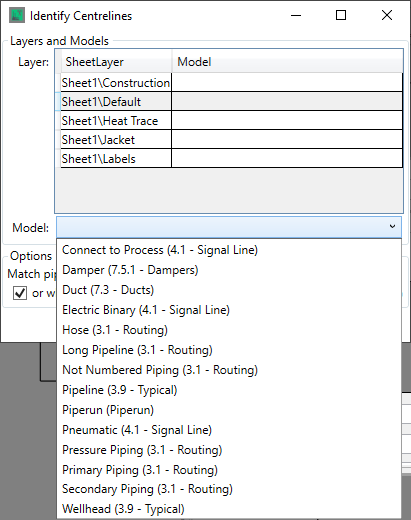
Note that line types are defined in the Model Library, in the Model Creation section.
With a model selected there are three options to be defined

These options enble you define the minimum length of line to be considered a piece of connector, in order to exclude flanges and break indicators, by defining its length, and the connectivity and gap size that means that two items are connected in reality.
Once these settings are made, or if the defaults are deemed acceptable, then clicking the ![]() button will identify all the centrelines on all of the layers as the model specifed for the centreline for each layer, based upon the distances defined in the options.
button will identify all the centrelines on all of the layers as the model specifed for the centreline for each layer, based upon the distances defined in the options.