Drawing Tools
Some drawings need to be altered in order to allow for faster and more accurate automation, the drawing tools provides a collection of functionallity to allow for creation or alteration of drawings.
When enabled from the views menu you will be presented with this panel shown below.
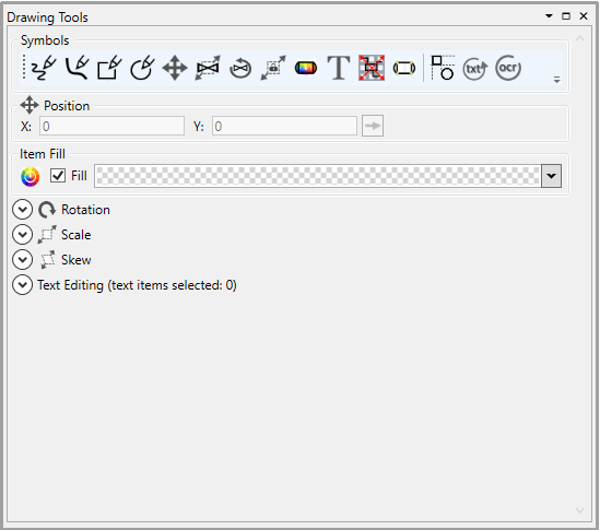
Here we will describe the functionallity this panel offers.
Draughting
| Icon | Description | Usage |
|---|---|---|
| Draw Line | Draws an equipment line or pipe line Enables the Drawing Options when selected Can be used with Orthogrophac Line to create vertical or horizontal lines The line type can be set to a pipeline with the pipeline option set. | |
| Draw Curve | Draws a 3, 5 or 7 point curve which can be a piece of equipment or pipeline Enables the Drawing Options when selected The line type can be set to a pipeline with the pipeline option set. | |
| Draw Rectangle | Draws a rectangle based on the settings defined in the draw shape options. Enables the Drawing Shape Option when selected Enables the Drawing Options when selected | |
| Draw Elipse | Draws an elipse based on the settings defined in the draw shape options. Enables the Drawing Shape Option when selected Enables the Drawing Options when selected | |
| Insert Text | Enable text to be placed on drawing at the location of the cursor when left clicked. will auto select the text once placed so that it can be editing in the text editing subpanel | |
| Fill Selected | Fills the graphic with the colour chosen in the fill section |
Draw Tool Options
Here you can set the line thickness and line colour.

Draw Shape Options
Here you can set the width and height of your rectangle or elipse. You can also choose to have the shape automatically filled with the colour you define.

Text Editing
When text is selected or new text is inserted the text editing section will populate, expanding it will give you access to some text editing/creation properties.
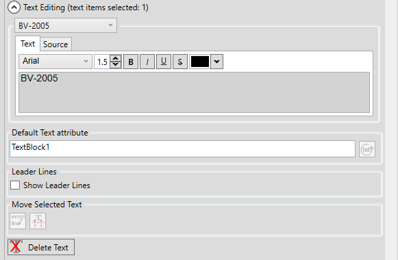
The dropdown menu will allow you to choose which piece of text you are working on if multiple are selected.
The text tab allows you to alter what the text says allowing with graphical information such as font, size, colour etc...
The source tab and default text attribute will allow you to set what engineering knowledge the piece of text is to represent to be used with the auto-label mapping functionallity.
Leader lines can be disabled or enabled for when the text has been mapped to the equipment or pipeline it represents.
Text can be merged, split or deleted in this subpanel by clicking the relative button.
Manipulation
| Icon | Description | Usage |
|---|---|---|
| Move | Enable the move handles for a drawing item that has been placed. Works with any Snap To functionallity defined Using the keybind Alt+D5 will enable this option | |
| Scale | Enables the scale handles allowing you to rotate visually See the Scale section for more precise scaling | |
| Rotate | Enables the rotation handles allowing you to rotate visually See the Rotation section for more precise rotation | |
| Aspect Ratio | Preserves the aspect ratio when using the scale handles | |
| Display Nodes | Display the path nodes for a drawing item to allow for movement of individual paths without needing to explode then re-join a graphical item |
Rotation
Expanding the Rotation section will give you access to some rotational manipulation.

Enabling the Auto Rotation option will force an item when moved to snap to the orientation of any line it intersects with.
Graphics can be rotated to any degree by setting the rotation ![]() then clicking the
then clicking the ![]() button.
button.
Alternatively you can use the quick rotate buttons described below.
| Button | Description |
|---|---|
| Rotate -90 degrees | |
| Rotate 180 degrees | |
| Rotate 90 degrees |
Scale
Expanding the Scale section will give you access to some scaling manipulation.

Grahics can be scaled in any direction by setting the X-Axis ![]() and/or the Y-Axis
and/or the Y-Axis ![]() then clicking the
then clicking the ![]() button.
button.
Alternatively you can use the quick scale buttons described below.
| Button | Description |
|---|---|
| Reduce the graphics size by 50% | |
| Increases the graphics size by 100% | |
| Mirror the graphic in the X Axis | |
| Mirror the graphic in the Y Axis |
Skew
Expanding the Skew section will give you access to some skewing manipulation.

Grahics can be skewed in any direction by setting the X-Axis ![]() and/or the Y-Axis
and/or the Y-Axis ![]() then clicking the
then clicking the ![]() button.
button.
Utility
| Icon | Description | Usage |
|---|---|---|
| Snap To | Enables the Snap Setup subpanel Enables snap to setting | |
| Design Lines | Enables or disable design lines Allows for quick and more precise draughting when used in conjunction with the Snap To Grid setting | |
| Text Replace | Enables text replace | |
| OCR | Enables OCR processing of rastered text |
Snap To Settings
When the enable snap button is pressed you will be able to access the snap to settings allowing you to define how the snap settings work.

You can alter how your snap to grid setting work by change the ![]() value. This is relative to your drawing grid setting size so 0.5 will be half of you grid setting defined for the drawing.
value. This is relative to your drawing grid setting size so 0.5 will be half of you grid setting defined for the drawing.
| Icon | Description |
|---|---|
| Enables Snap To Grid when drawing or moving an item | |
| Displays the boundary box used when determining snap location | |
| Displays the snapping points when moving an item |