Auto Branch & Break Creation
Default Model Setup
The Model Setup is used to define the models to be used for the inline break point, the 3-Port Branch and 4-Port Branch Models

To do this, select the model you wish to use from the drop-down, or by typing its name.
Note that the 4-Port Branch creation is an optional step, as these are uncommon on drawings, and can be created erroneously if lines cross without being properly broken.
Once you have set the models, clicking ![]() saves the models, while clicking
saves the models, while clicking ![]() exits the window without saving.
exits the window without saving.
Generating Branches
Drawings imported to Aurelia do not have their piping branches configured by default, once you have identified the pipe runs, it is important to run the automatic branch creation, in order to ensure full connectivity on the Drawings.
Once the P&ID has opened select “Generate Branching Points” from the Drawing Tools menu
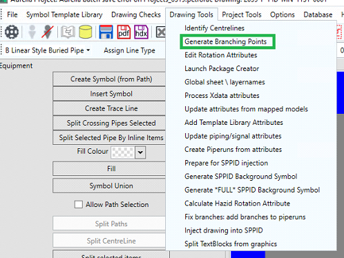
You may be prompted to define the 3 and 4-port branch models, if they have not already been defined
Generating Breaks
When the break labels have been correctly configured (see the How-to guides on Regioning and Symbol Identification for this process), there is the facility within Aurelia to automatically place breaks within lines, based upon the location of the break symbols. Note that the equipment on the drawing needs to be mapped to EI models for this operation to be successful.